Thursday 29 October 2015

TIE Cockpit Progress


The cockpit is taking shape now.  The console is filling the space better, now with pedals below.  So much extruding for the console shape, I want to give quite a claustrophobic feeling, but also functional, everything within arms reach.

I'm happy with how it's turning out, there are no glaring errors jumping out at me.

Tuesday 27 October 2015

TIE Cockpit Model


Here are the beginnings of my TIE cockpit!  The octagons are to show the back and windscreen of the TIE.  I'm pleased with how my console is turning out, but it needs more buttons, screens, and dials, so that it looks more high tech and space-like!  Also, the chair will be remade, I showed a friend and they weren't overly impressed with the Empire's funding...using cheap, unstable chairs...

Lathe Joysticks

Using the lathe tool, I created the rubber aspect beneath the joystick.

By drawing a spline and then revolving, moving the revolved polygons to the edge, otherwise I had an hour glass looking shape.

Making them this way is far quicker than if I were to try using cylinders, setting the height segments to 6 and the grabbing the vertices and bring them in, then out, then in etc.  Plus I've learned a new technique using lathe!

TIE Cockpit


For my 3rd model I have decided to create an interior of a TIE Interceptor cockpit.

Through my research I have not found many views of the TIE interior.  After discussing with my lecturer, it has been decided that I can create my own interpretation of what a TIE interior may look like.

I have found this screenshot, which I presume is from an old game cutscene, that only shows a limited perspective of the cockpit.  I can take some information from this, but only to a slight degree.


Where as this GIF shows quite a lot more detail of the cockpit, the different screens flashing up, and as it pans slightly to the left, it shows more depth.  This give me a good basis to begin my model and try to replicate and adapt the cockpit to my own design.


References:

[cockpit tie fighter pilot] n.d. [online] Available at: <http://www.miscellaneoushi.com/Clothes/tie/cockpit_tie_fighter_pilot_1920x1440_wallpaper_22622/download_1080x960> [Accessed 27 October 2015]

[Cockpit View from a TIE Fighter] n.d. [online] Available at: <https://s-media-cache-ak0.pinimg.com/originals/44/83/ea/4483ea50d2aa34b3bacb78d1dfaff185.gif> [Accessed on 27 October 2015]

Sunday 25 October 2015

TIE Wing Overhaul

I couldn't salvage the wings.

I have had to recreate them, and by doing so, I have made them much quicker, and much nicer than before.


The top wing is the new one, and the bottom is the old.  The shape is much nicer, and because I've made it straight, rather than at an angle, it so much easier to work with.  Extruding polygons in, out, up, or down is now a breeze.  Rather than having to move objects to the side, and then up, and then to the side again.  I know now, keep objects flat until they are complete before rotating.

Thursday 22 October 2015

Miniature X-Wing

Having miniatures to look at, helps find all the smaller, finer details.


From the side view here, I noticed that the X-Wing has little rivets down the fuselage, something I may have missed before.  The details such as the square holes in the underside of the wings were too hard to read on the schematics I was using.  Seeing this model with the holes makes it that much easier to work out what they are.

The back view I can see the details on the rear of the X-Wing, making them much easier to create. I think the best way to make these would be to create the primitive shapes separately and then using boolean > union to make them a part of the main body.


The top view shows all the detail in between the engines on the wings much clearer to see.  Again I would create these shapes using primitives, and joining them to the main body through boolean > union.


One thing I have noticed on the front view are the little braces (I think they are) on the front of the wings' engines.  They all tilt towards the ship, so when making one I would need to rotate it and then when using the mirror tool, they should all match up and be tilted towards the main body.

Miniature TIE


To achieve the finer details I have taken some photos of a miniature TIE Fighter.

The wings here are more detailed than I had realised, I would need to inset the darker areas, and then use the connect tool to create the ridges.
 Using the edges, I can grab the edges of the thruster and create the grip looking shapes into the main body.
The front view shows the connections from the windscreen port to the main body, this could be achieved via extruding the windscreen or adding the shapes then using compound > boolean > cut > union to mold the shapes together.
To achieve the greater detail in the entrance hatch, I believe I would be able to use the boolean tool, under the compound objects, and then use the cut: union to add the shapes on top.

Wednesday 21 October 2015

X-Wing Progress


Here is my X-Wing in it's current state.  All of the basic shapes have been created, now things need refining and neatening up.  The wings need a lot of attention, but I thought I would mirror them and get them all in so I can see how far I am getting with the model.  Doing that has helped visualised the end result.


The front view; you can see that the fuselage needs some refining to the shape, this can be done by selecting the edges and bringing them in, using the reference image behind as a guide.  Incidentally, there are a lot of unnamed objects in the object list, if this isn't fixed soon, I'll lose what objects are what.


Storyboard

I have written up some storyboards for the animation part of the assessment.  The idea is to show a chase between a TIE Interceptor and an X-wing.  I want to incorporate some live action into the animation, just of some arms controlling the TIE, pressing switches and using the thrusters, etc.


Tuesday 20 October 2015

X-Wing

For my second model I want to create an X-Wing.

Looking at the image, I can see 4 main parts to the ship: the fuselage, the engines, guns, and wings.

The majority of these can then be cloned once I have one completed, saving lots of time.


References:

[X-wing_Fathead] n.d [online] Available at: <http://vignette1.wikia.nocookie.net/starwars/images/8/80/X-wing_Fathead.png/revision/latest?cb=20131012080921> [Accessed 20 October 2015]

Sunday 18 October 2015

Tie Interceptor Progress

The TIE interceptor is looking much better now...


For now I've just changed the colour of the objects, in the inspector on the right.  Just by doing that it gives it a much more complete look.  So far I'm happy with how it's shaping up...but the wings, the wings are a pain! There are a lot of useless edges where the points meet at the tip.  I think I need to address this, as it looks untidy and makes editing it very troublesome.

Thursday 15 October 2015

Mood Board


If my initial idea can go ahead, I want to look into G-LOC, when a pilot falls unconscious due the G-force exerted upon them, leading to grey outs and loss of consciousness.

Following on from the loss of consciousness, I would like to them portray from a POV of the pilot as he/she regains consciousness, before the visuals are stabilised.  The way the colours are looking smudged across the viewers lens is something I would like to recreate.

This picture of Elite: Dangerous shows that space doesn't have to be pitch black, the use of colour to represent space dust would make space intriguing and interesting to look at.  Also this is a chance to have different colours reflecting off of the ship's metallic surfaces.

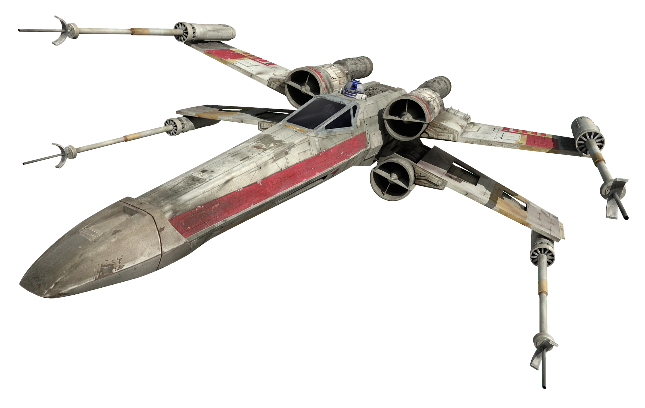
I want a metallic colour for the spaceships, but nothing too shiny, a dark strong metal colour to look heavy, and tough, so that it looks like it could withstand a blast from a laser.

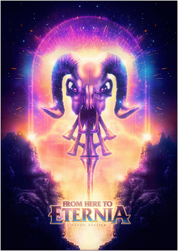
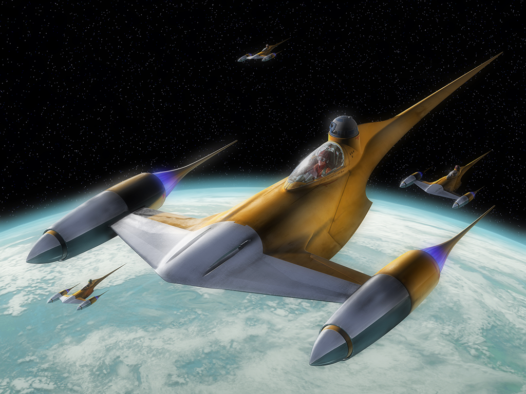
Again, this another picture where the colours really jump out and make the whole composition more intriguing and interesting to look at.  Also the use of colour, blacks, purples, into orange, golds, and yellows.  The yellow and purple sit opposite each other on the colour wheel, so using them together makes them stand out from one another, and add a nice contrast.  For example using a gold palette for a sun, and then a deep purple for the space, would make the sun glow against the purples.  And when the colours blend, they make a myriad of colours in between, as opposed to using black for space, as all that would happen is that the golds would get darker until black.

Here, is a still of a centrifuge, demonstrates the use of motion I want to incorporate into my animation, of having the pilot spinning out of control in the ship.  This picture has strong blur, due to the colossal speeds of the centrifuge, which would make the motions of an out of control ship look smoother and more realistic.


The inside of the TIE cockpit, with the pilot surrounded in a claustrophobic sphere.  The blacks and the reds really stand out from one another.  With an actor and props I would like to recreate a similar looking helmet/suit to then composite them in the cockpit.


References:

[Time Tolerance Curve] n.d. [image online] Available at: <http://www.avmed.in/wp-content/uploads/2012/06/G-Time-Tolerance-Curve.jpg> [Accessed on 20 October 2015]

[Blurred Vision] n.d. [image online] Available at: <https://edc2.healthtap.com/ht-staging/user_answer/avatars/1875229/large/open-uri20140711-26764-1gg72g2.jpeg?1405049342> [Accessed on 21 October 2015]

[Elite: Dangerous] n.d. [image online] Available at: <http://cloud.attackofthefanboy.com/wp-content/uploads/2015/01/elite-dangerous-small-370x208.jpg> [Accessed on 21 October 2015]

[Metal Metallica Reflective] n.d. [image online] Availabe at: <http://s3.amazonaws.com/everystockphoto/fspid30/25/30/03/3/metal-metallic-reflective-2530033-o.jpg> [Accessed on 21 October 2015]

[From Here to Eternia] 2011 [image online] Available at: <https://www.behance.net/gallery/From-Here-To-Eternia/1015941> [Accessed on 22 October 2015]

Crisman, C. 2014. [image online] Available at: <http://www.wired.co.uk/magazine/archive/2014/08/features/space-health> [Accessed on 22 October 2015]

[Review_ImperialTIEFighter_still02] n.d. [image online] Available at:  <http://www.jeditemplearchives.com/galleries/2010/Review_ImperialTIEFighter/Review_ImperialTIEFighter_still02.jpg> [Accessed on 22 October 2015]

Solution to One Problem...


I had the problem of drawing a line, and then expanding it to create the TIE Interceptor wing, which after fiddling, worked.  Now as it was a line, the front was open, I have remedied this, but not in the best way.

The gap is closed, but when the vertices/edges are visible it looks quite messy, hopefully this wont cause an issue when texturing...

As all vertices were put in the middle, I selected them all and collapsed them, so that they are now one vertex.  Doing this makes sure there are no extra, or redundant, vertices.  Extra vertices can cause issues, and take up memory.

Wednesday 14 October 2015

The TIE Intercepetor


I have been creating my TIE Interceptor, and the majority of things have been going well...

Using primitive shapes to create all the base shapes, and then extruding various polygons, connecting edges, and so on to create more complex shapes.

(TIE Interceptor 4 view layout)
A problem I have run into when creating is that I can only find 2 views for the schematics, front, and side.  If I had the top view as well some of the parts would have been so much easier, such as the hatch on top, or lining up details on the sides of the wings.

But only using 2 has worked well enough for me to be able to create what I have made thus far.


Something else that has been difficult is creating the wings, as they are at an angle that using the primitives was proving very testing.  For the screenshot on the right, I used the line shape, made it rectangular and then extruded the polygons to give it thickness.  Now the trouble is the odd shape at the tip, which will need closing.


To the left is the shapes expanded showing the groups and to the right is the groups collapsed.  Prior to grouping all the different objects, they were descending alphabetically, so objects that may be together on the model were either end of the list, which makes things very confusing.  Naming and grouping has helped so much when looking for the various shapes, otherwise it would have been a case of clicking on objects and seeing what lights up, which is a massive waste of time, and if this were a real world project, it would be a waste of money.


Saturday 10 October 2015

Low Poly House


For an exercise to get started with 3DS MAX we have to make a low poly house following instructions.

We started with just a cube and had to keep extruding new parts of the polygons to add more sections.  Doing it this way it keeps everything as just one shape, as opposed to have a list of different boxes, or other shapes.  As you can see to the right there is just the one box in the scene.

A great technique shown in the instructions was the connect tool.  Having the object as an editable poly and the selecting the edges you want to connect, simply click connect, and another edge is placed perpendicular to the original edges


Using the connect tool it made it incredibly easy to create the windows, as the edges above the windows were selected, and then connected, once the dialogue box had opens I specified 2 edges and changed the amount of pinch, and their location on the original edges.

I could then extrude them into the cube and again using the connect tool I could create the parts of the frame.

To create the lip on the roof, I used the bevel tool, this helped as I didn't need to make an separate object as the roof with a larger area.  I extruded slightly, within the bevel tool, and bevelled outwards, you can also bevel inwards to create a smaller surface if you wish.


Using all of these techniques, to create the house was a real help and great way to be introduced to program, as by using these it gives a basic understanding of how to use the dialogue boxes.  Many of the operations in 3DS MAX use the dialogue boxes, now I know how they work, I can begin to experiment with other tools.


Thursday 8 October 2015

Looking at Using Primitive Shapes to Start


After some more practice with 3ds Max, I have created a maritime steering wheel, 'free hand' (as opposed to using schematics to create over.  Using these would make it much more accurate.

Here is the wheel that I created.  For this all I used were tubes, and cuboids.  The inner rings were created firsts, and then I copied and scaled it up to create the outer ring.  To make the straight posts, I put the different primitives and the grouped them, so that it becomes one object. Lining it up in the centre and then, when clicking on the object, holding shift and then dragging, it causes the object to be copied, or referenced, which was the use I needed as I could specify the amount necessary and they are all spaced equally.

(bp-setup-01, n.d.)
If I were to use a schematics when making the steering wheel, such as the car to the right,  I would have been able to create the shapes, by dragging the edges, vertices, or polygons to match the picture(s)

Once I had an idea of using primitive to make 3d objects.  I decided to look up a Tie-Interceptor and then draw over primitive shapes to give a rough idea how I could make the Tie-Interceptor using the primitive shapes, to keep the object simple, and to try and keep the polygon count down.

(Tie-Interceptor, n.d.)

This is the original schematic of the Tie-Interceptor, showing the front and the left hand side.

Using this image, it is easier to see which primitive shapes can be used to create each part of the ship.  For example, the cock pit would be a sphere, and the arms could made from tubes (as highlighted in the picture below).

Doing this prior to making the object makes things much quicker when going into 3ds Max, as I can have a print out on hand to reference.


(Tie-Interceptor, n.d.)


References:

[bp-setup-01] n.d. [online] Available at: <http://www.the-blueprints.com/modules/tutorials/images/tut-3dmax/bp-setup-01.GIF> [Accessed on 09 October 2015]

[TIEint_schem] n.d. [online] Available at:  <http://vignette2.wikia.nocookie.net/starwars/images/7/7a/TIEint_schem.jpg/revision/latest?cb=20081030151146> [Accessed on 09 October 2015]


Getting Started


Today we had our first practical session.

It's been about 4 years since I have last used any 3d design software, I dabbled in a bit of Maya in an old job...

The interface when at first glance is quite intimidating, as there are lot of buttons, with ambiguous icons.  First discussed was the layout of the screen, and what some of the buttons do on the main toolbar, located under the File, Edit, etc tool bar.


From my lecture, and practical, the most necessary buttons I shall be using are: undo, redo, move, rotate, scale, and snapping.

Something else to keep an eye on is that unlike Unity, where in 3d space, x is horizontal, y is vertical and z is depth, in 3ds Max when creating a shape, it appears the z is the vertical and y is the depth.  That is due to the grid (you can see on the bottom right window of the picture above) lays flat in the space so that the x and y axis follow the black lines in the centre of the grid, and by doing so the z axis appears to rise upwards.

The four-view port layout

We were set an exercise to create a maritime steering wheel in 3ds Max, using primitive shapes.


I first set about this by finding a suitable image and then trying to recreate it using the primitive shapes, to get a feel for 3ds Max.

I quickly noticed that it can be quite difficult to line up shapes together, using the four-view port layout makes this much easier.


(Nautical Ship Wheel, n.d.)


From this screenshot, I have the four-view layout, trying to line up the pole onto the central ring.  If were not to use this layout, just using perspective may look like I have it laid up correctly, but hen from another angle it wouldn't marry up.  Having to keep panning the camera around to line things up would have taken so much longer.  Using the four-view layout the top screen and left screen made this so much more accurate, and quicker for me to line each shape up precisely.


[Nautical Ship Wheel] n.d. [online] Available at: < http://ancientpoint.com/imgs/a/h/f/u/i/ship_wheel_18inches_nautical_ship_wheel_boat_steering_wheel_maritime_decor_gift_3_lgw.jpg> [Accessed 05 October 2015]

Monday 5 October 2015

Start of a new year, start of a new project


The first day back, I have been given my current assignment: To create a 3D model of a vehicle from the Star Wars universe.  To which I am looking forward to, had it been too open, it would have been very difficult to zero in on one idea, that 1, would look good, and 2, not be too difficult to create.

As I have to create a vehicle of some sort, it makes it easier when having to break the object down into the 10 primitive shapes: box, sphere, cylinder, torus, teapot, cone, geosphere, tube, pyramid, and plane.

Having the week to think upon this, I have been looking at the various different types of vehicles, from the original trilogy, to the new(er) trilogy.  It seems that the original trilogy's vehicles had more hard edges, as opposed to the new(er) trilogy's vehicles seeming more rounded.  I imagine advances in (our) technology had a hand in this, CGI design as opposed to miniatures. 

(Man in Middle, n.d.)

This image shows vehicles from the original series, and it's quite easy to see that a lot of these have a lot of flat paneled exteriors.

Where as this picture of the N-1 Starfighter, from Episode 1, has very smooth edges that all mold together, looking much sleeker.

So after looking around, I think, it might be wiser to create vehicle from the original series as they are more primitive with their use of shape, so that way it may be easier to create a more accurate 3d representation.


(N-1 StarFighter, n.d.)

Research Board:


(X-wing, n.d.)


(DESTROYER, n.d.)


(AT-ST, n.d.)


(Speeder Bike, n.d.)
If I were to create a speeder bike, it would have to be sans rider, as a part of the brief says that we are not to submit humanoid models.


(Star Wars Droids, n.d.)


References:

Autodesk. n.d. Standard Primitives. [online] Available at: < http://docs.autodesk.com/3DSMAX/15/ENU/3ds-Max-Help/index.html?url=files/GUID-66152BDE-BA64-423F-8472-C1F0EB409E16.htm,topicNumber=d30e26059>  [Accessed 04 October 2015]

Pictures:

[Man in Middle] n.d. [online] Available at: < https://futureofstarwars.files.wordpress.com/2014/10/starwarsprops-maninmiddle.jpg> [Accessed 04 October 2015]

[N-1 Starfighter] n.d. [online] Available at:< http://img4.wikia.nocookie.net/__cb20130619201428/starwars/images/6/64/N-1_Starfighter.png>
[Accessed 04 October 2015]

[Xwing] n.d. [online] Available at:<http://application.denofgeek.com/images/m/75spaceships/main/xwing.jpg> [Accessed 04 October 2015]

[DESTROYER] n.d. [online] Available at: <http://manilovefilms.com/wp-content/uploads/2013/03/DESTROYER.jpg> [Accessed 04 October 2015]

[AT-ST] n.d. [online] Available at: <http://img2.wikia.nocookie.net/__cb20130903201709/starwars/images/6/6b/AT-ST_SWGTCG_art.JPG> [Accessed 04 October 2015]

[Speeder Bike] n.d. [online] Available at: <http://vignette1.wikia.nocookie.net/starwars/images/1/10/74-Z_Military_Speeder_Bike.jpg/revision/latest?cb=20130410040107> [Accessed 04 Ocotber 2015]

[Star Wars Droid) n.d. [online] Available at: <http://crystaltips.typepad.com/photos/uncategorized/starwarsdroid.jpg> [Accessed 05 October 2015]